Erin Rose
ErinRose@chaos.social
noise cancelling headphones are great, but I'm now a far worse CNC machine operator/carer - drowning out their cries of "mother! please! turn the feed-rate down!"
 2
2
 1
1
 0
0
Andrew Zonenberg
azonenberg@ioc.exchange@ErinRose It's funny how wide the variation in machining scales/tolerances is.
Like, I completely ignore all of the normal feed rate recommendations on my mill because I'm taking such light cuts (last time I used it I was doing 5-10 μm passes towards the end after having started with 50 μm depth per pass)
2
0
0
Andrew Zonenberg
azonenberg@ioc.exchange@ErinRose also trying to do 5 μm passes on a manual mill with 1mm/div handwheels divided into 100 ticks is tricky to say the least lol.
But when you're trying to hit (but not penetrate) a copper foil something like 15 μm thick, your Z axis tolerance is in fact that tight
1
0
0
Erin Rose
ErinRose@chaos.social@azonenberg The CNC I currently use when I'm at home is a little 30cm³ othermill.
The recommended feeds and speeds for soft metals are incredibly conservative, so It's pretty wild how well it handles being pushed far past them with a plastic chassis and a drone motor spindle..
1
0
0
Andrew Zonenberg
azonenberg@ioc.exchange@ErinRose My problem with mine is the spindle runout. I have some 100 μm endmills but I keep breaking them because they flail around so much in the stock Sherline spindle (it also hits like 4000 RPM or something max and these tiny mills really want to run at like 100K). But the TIR is probably in excess of 10 μm which is fine for a normal cutter but absolutely intolerable for something this small. I don't actually have a number for TIR because I don't have an indicator with enough significant digits but I can see it wobbling under the microscope.
I do most of my work these days with 250 μm endmills which I have broken a handful of times, but they generally run decently well on the platform.
1
0
0
Andrew Zonenberg
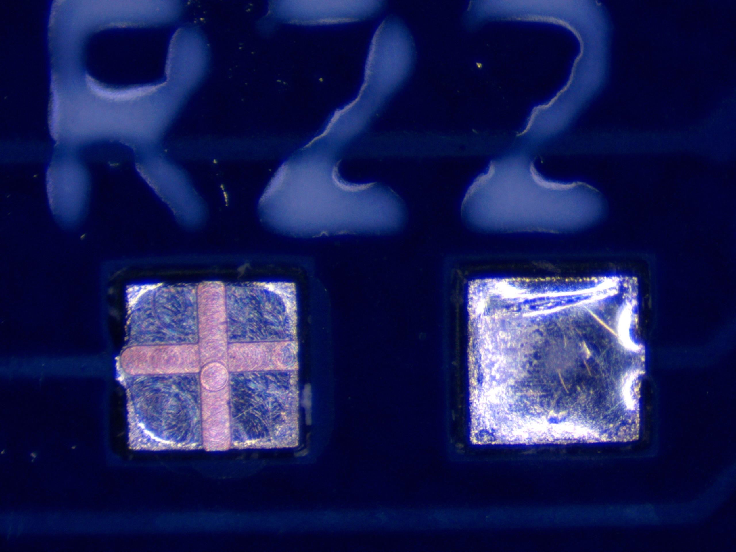
azonenberg@ioc.exchange@ErinRose 0402 SMT resistor footprint faced flat with a 250 μm endmill, then used a 100 to mill the + into the solder layer and expose the copper.
Just practicing, not a real bodge job. The 100 μm endmills allow absolutely surgical work if you can get them to not snap, but I need a spindle upgrade to use them properly
 1
0
0
1
0
0
Erin Rose
ErinRose@chaos.social@azonenberg okay that is extremely cool!
I machine a lot of PCB's for mechanical prototyping, and occasionally functional boards, but I never considered the potential uses for rework.
1
0
0
Andrew Zonenberg
azonenberg@ioc.exchange@ErinRose H/o you need to see some of the stuff i've done for ECOs on prototypes lol.
1
0
0
Andrew Zonenberg
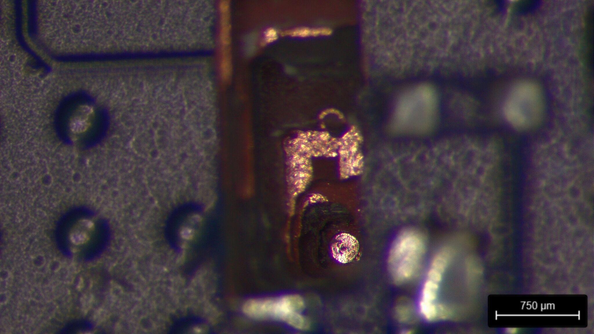
azonenberg@ioc.exchange@ErinRose This is probably one of my most challenging circuit edits, adding a new via-in-pad under a 484 ball BGA on a populated ten layer board to break out a SPI chip select that had been miswired.
I had to dodge JTAG and some other signals while drilling up to the back side of a BGA land and then solder a wire to the underside of the land at the bottom of a 1.6mm deep cavity then reconnect it to a surface trace.
 1
2
0
1
2
0
Andrew Zonenberg
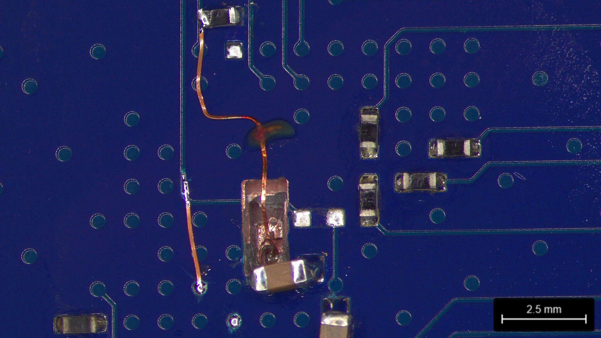
azonenberg@ioc.exchange@ErinRose The finished bodge before filling with epoxy
 2
1
0
2
1
0
Andrew Zonenberg
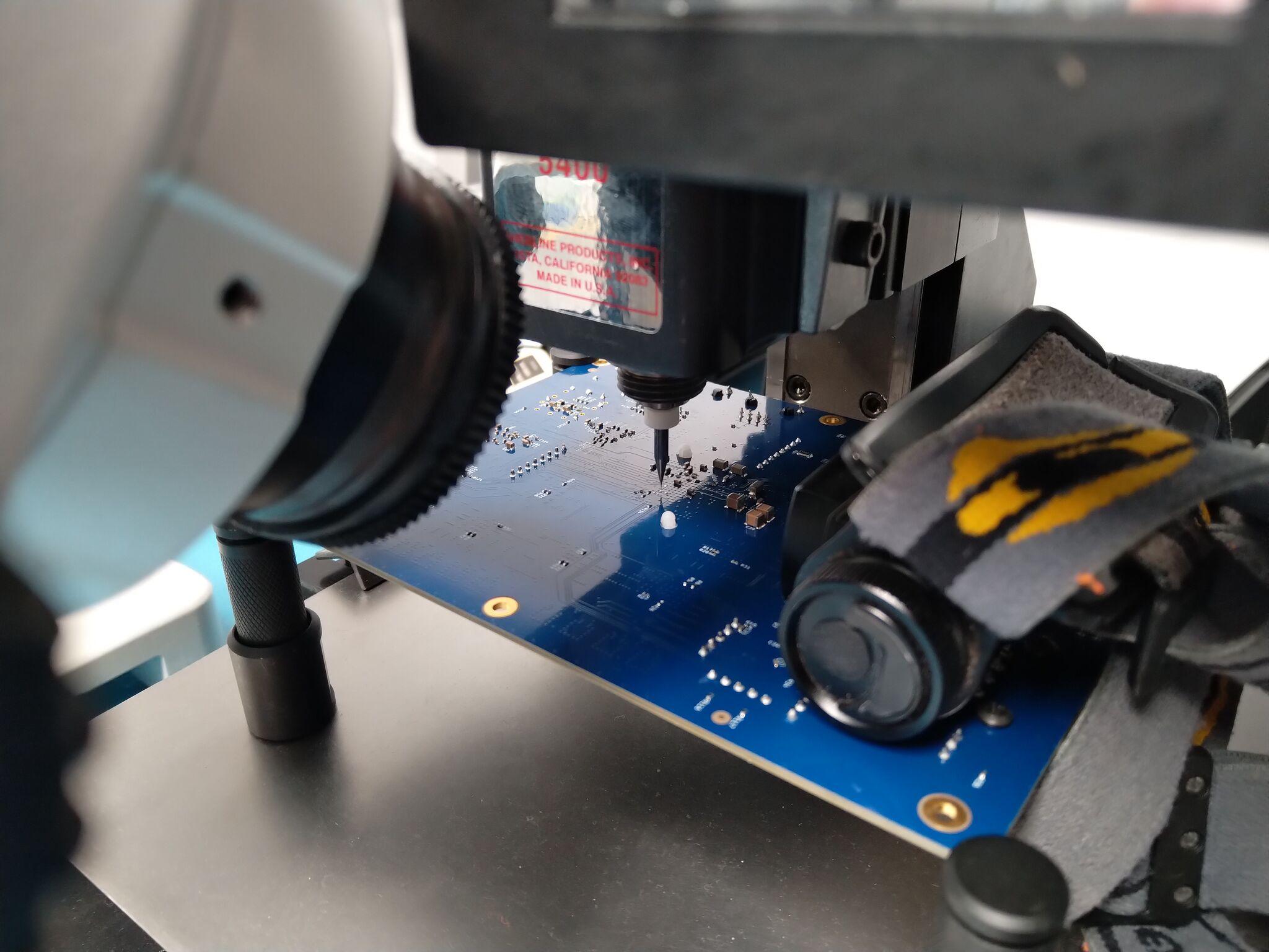
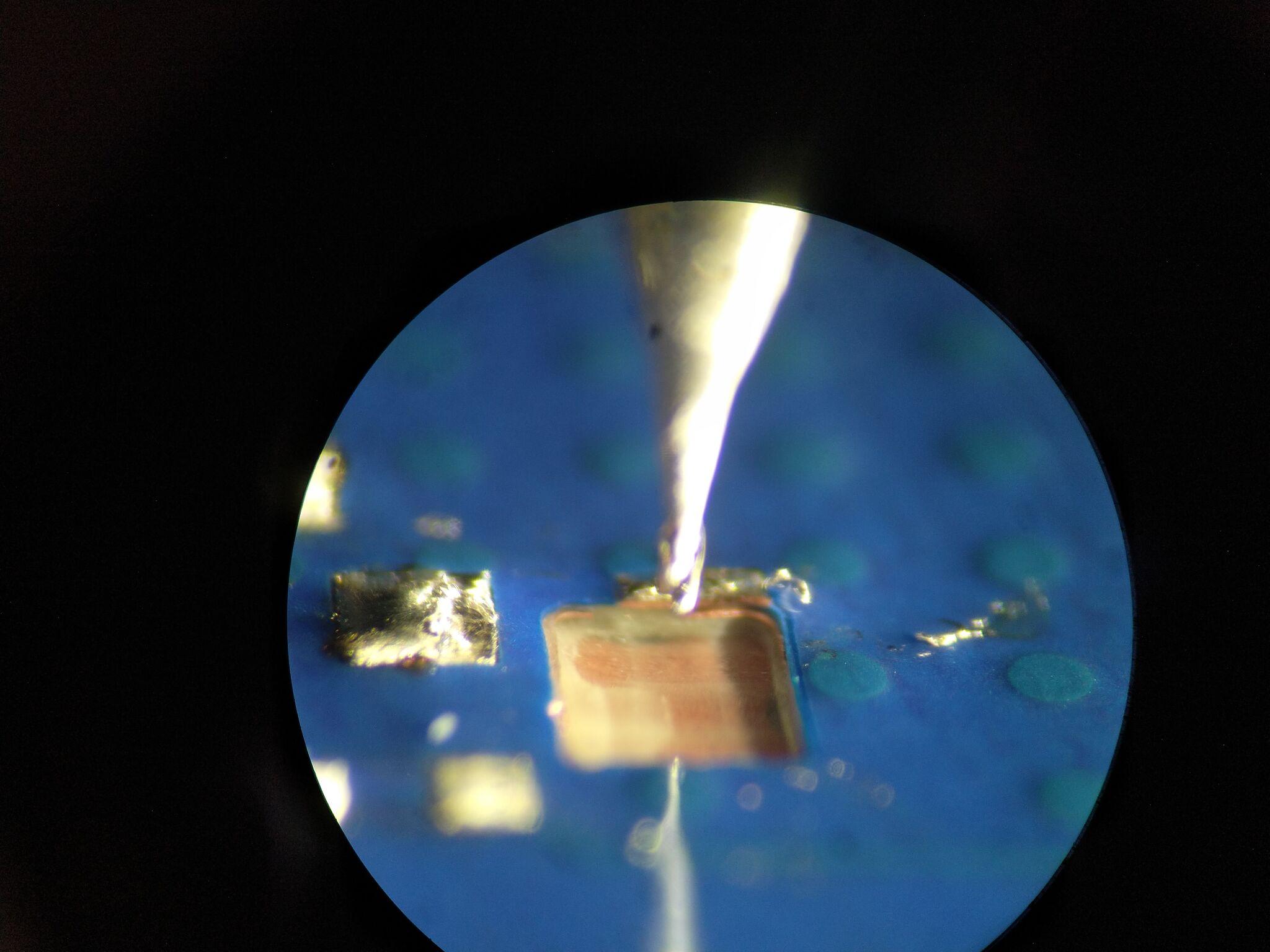
azonenberg@ioc.exchange@ErinRose And here's the setup, this was using a random LED headlamp since I didn't have a gooseneck lamp on this bench yet
 2
0
0
2
0
0
Andrew Zonenberg
azonenberg@ioc.exchange@ErinRose Last week for a $dayjob project I even machined into a multi-die IC package so we could probe some die-to-die signals on the substrate that were not brought out to package pins.
Can't share the pics of that one sadly, yay NDAs. But it was a fun project
0
0
1
James Morris
jmorrisRE: https://ioc.exchange/@azonenberg/115962847027721998
1
0
0
Andrew Zonenberg
azonenberg@ioc.exchange@jmorris Yep the current setup is a Sherline 5400. The axes are fine but I want a higher RPM, lower runout spindle retrofitted.
0
0
0
Laura
la@chaos.social@azonenberg @ErinRose I can definitely recommend setting up an indicator for that sort of stuff.
And at those scales a millimess or something equivalent will also work well
1
0
0
Laura
la@chaos.social@azonenberg @ErinRose fair enough... I'm usually more around 500mm^3 of material removed per second....
1
0
0
Andrew Zonenberg
azonenberg@ioc.exchange
2
0
0
Laura
la@chaos.social@azonenberg @ErinRose I mean, 5 microns are well within indicator range. The finest resultion I've seen (on a mechanical indicator) is 100nm. Admittedly, those are quite bulky, but the mahr millimess series goes down to 500nm, in a reasonable package.
(I still have an lvdt amp I need to fix and those go down to single digit nm scales)
1
0
0
Laura
la@chaos.social@azonenberg @ErinRose Iiiiiii don't understand why that matters. Would you set your indicator up against the part? I thought the discussion was about advancing an axis by a small amount. So I'd just set it up on a flat surface of the sled (in this case your Z axis i'd assume)
But I suppose I missunderstood the problem?
1
0
0
Laura
la@chaos.social@azonenberg @ErinRose nono. But in my experience the problem of overshoot on a small handwheel is a lot less prevelent when you have a direct reading (as in not affected by backlash and stick-slip) way to see what your doing.
1
0
0
Andrew Zonenberg
azonenberg@ioc.exchange@la @ErinRose Oh. That's why I have the microscope, I'm not targeting a specific dimension I'm trying to hit a copper feature I can see.
So i can ignore backlash etc and just look at relative positions of the cutter and the feature for x/y.
And for z look at when the copper turns shiny (often I don't know actual as fabricated z axis dimensions to this tolerance so even if i had a suitably accurate DRO it wouldn't help as I don't know exactly where the target is, i just know when I've hit it)
1
0
0
Laura
la@chaos.social@azonenberg @ErinRose Oh. I see. Yeah, no makes sense why an indicator wouldn't help you....
0
0
0
@azonenberg @ErinRose
Not that you say it out aloud.
Yeah.
That does make sense.
I suspect it also says that it's time for bed in my time zone.
0
0
0
Andrew Zonenberg
azonenberg@ioc.exchange@krahabors It's rectangular wire specifically meant for this sort of rework so it'll lie flat on the board and be less likely to snag (and easier to fit under stuff)
0
0
0