gigabecquerel
gigabecquerel@chaos.socialScience is cool!
And this thing here even more so.
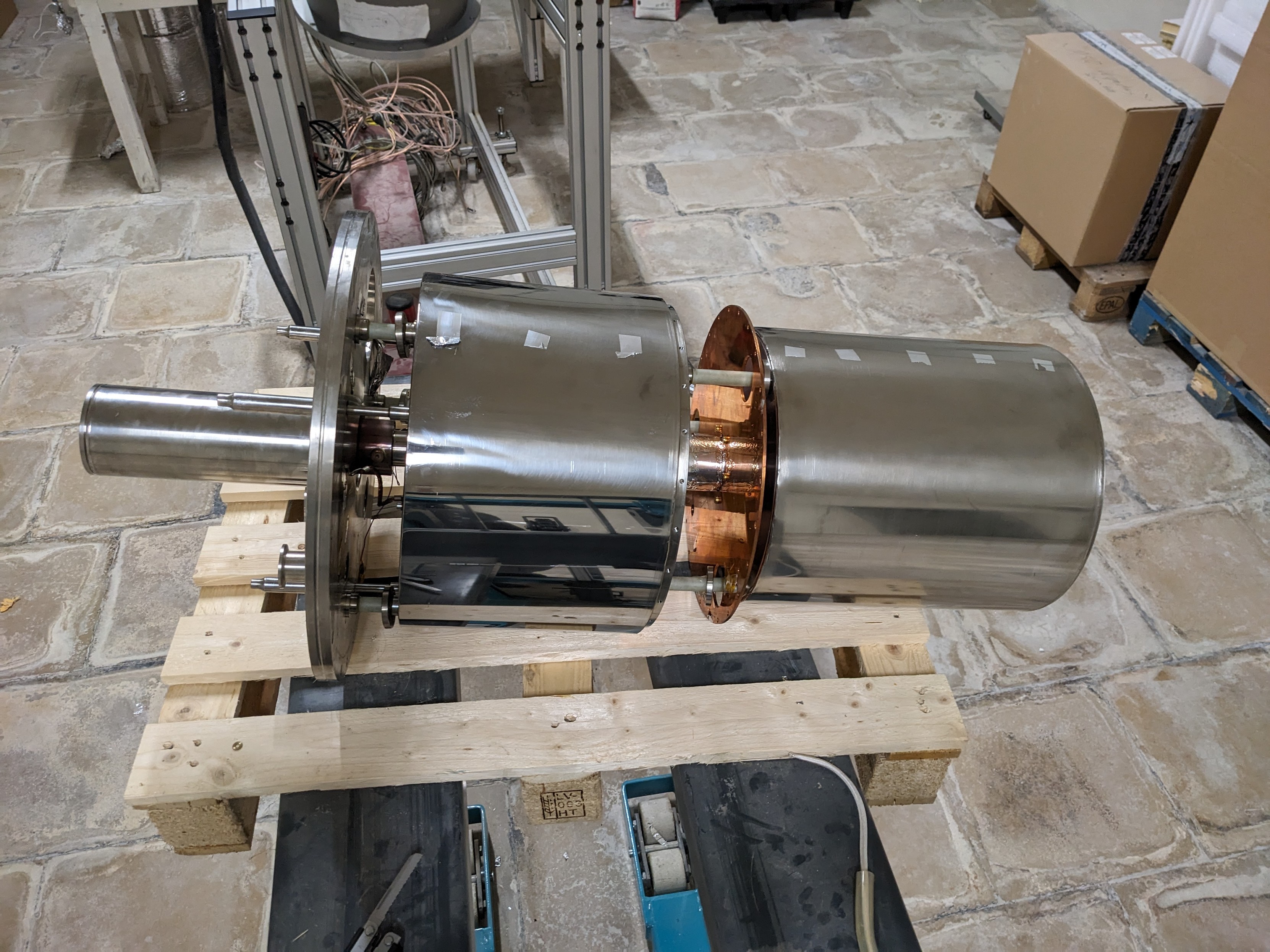
I got to take apart an Adiabatic Demagnetisation Refrigerator Cryostat with the wonderful @stdlogicvector , a small cryostat that was used to cool a transition edge sensor to ~40 mK.
It works by applying a magnetic field to some funny materials, and when removing that field the material cools down below its original temperature, which is 4.2 kelvin in this case.
The main cooling is done by a huge amount of LN2 and LHe.
gigabecquerel
gigabecquerel@chaos.socialThere was some kind of experiment left over in there, I'm guessing it's a remnant of the CRESST experiment, a crystal, a collimator and a photodiode, so maybe scintillation yield measurements?
gigabecquerel
gigabecquerel@chaos.socialThe entire cryostat consists of an LN2 tank which provides heat shielding and a LHe tank as a "warm" stage. The bottom of the LHe tank forms the base plate and thermal anchor where everything is bolted onto. Inside the tank is the ADR Magnet which we'll get to in a minute. Inside the magnet bore, held by kevlar strings, is the ADR itself. Everything is wrapped in foil for thermal insulation.
gigabecquerel
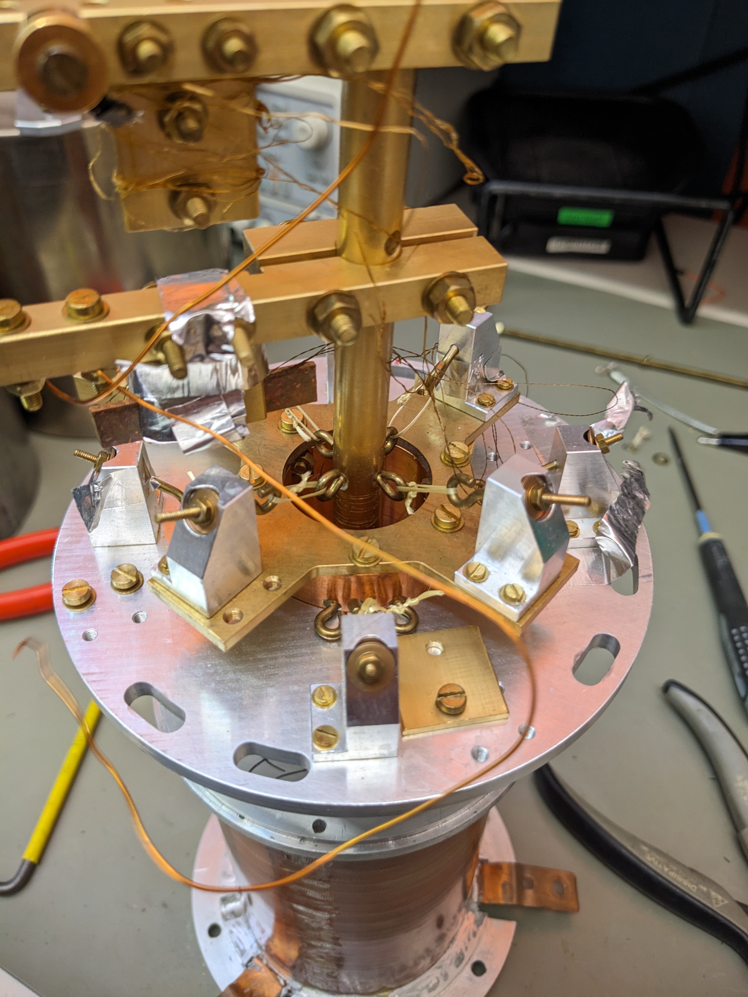
gigabecquerel@chaos.socialThis is the thermal switch. It links the ADR thermally to the 4k stage when everything is being cooled down and while the magnet is being ramped up. Then the switch opens, separating the ADR themally and letting it cool down below 4k when the magnet is ramped down again.
gigabecquerel
gigabecquerel@chaos.socialThe cryostat coinsists of many layers, it's built like an onion.
This serves to reduce thermal load vial radiation, with the 77k stage sinking the biggest load, after all, LN2 is a lot cheaper than LHe.
gigabecquerel
gigabecquerel@chaos.socialThis is the magnet itself. As stated earlier it's entirely submerged in LHe to cool it down, afaik it's NbTi used at up to 7 T. It has to be in LHe because its critical temperature is around 10 k.
Interestingly enough it consists of two separate windings with entirely different construction! Maybe one was added later for higher fields, but I don't know
gigabecquerel
gigabecquerel@chaos.socialAnd here, finally, is the ADR itself.
At this point I was pretty tired and forgot to take pics of the good stuff :<
You can see the two stages hanging on kevlar threads, the entire assembly would be sitting inside the magnet bore in its original position.
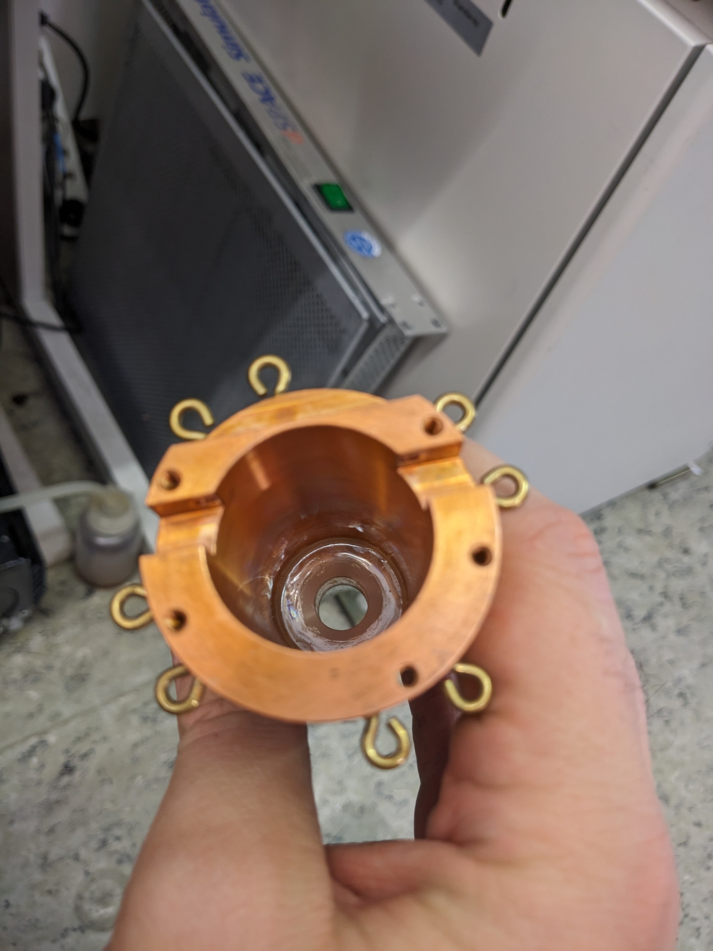
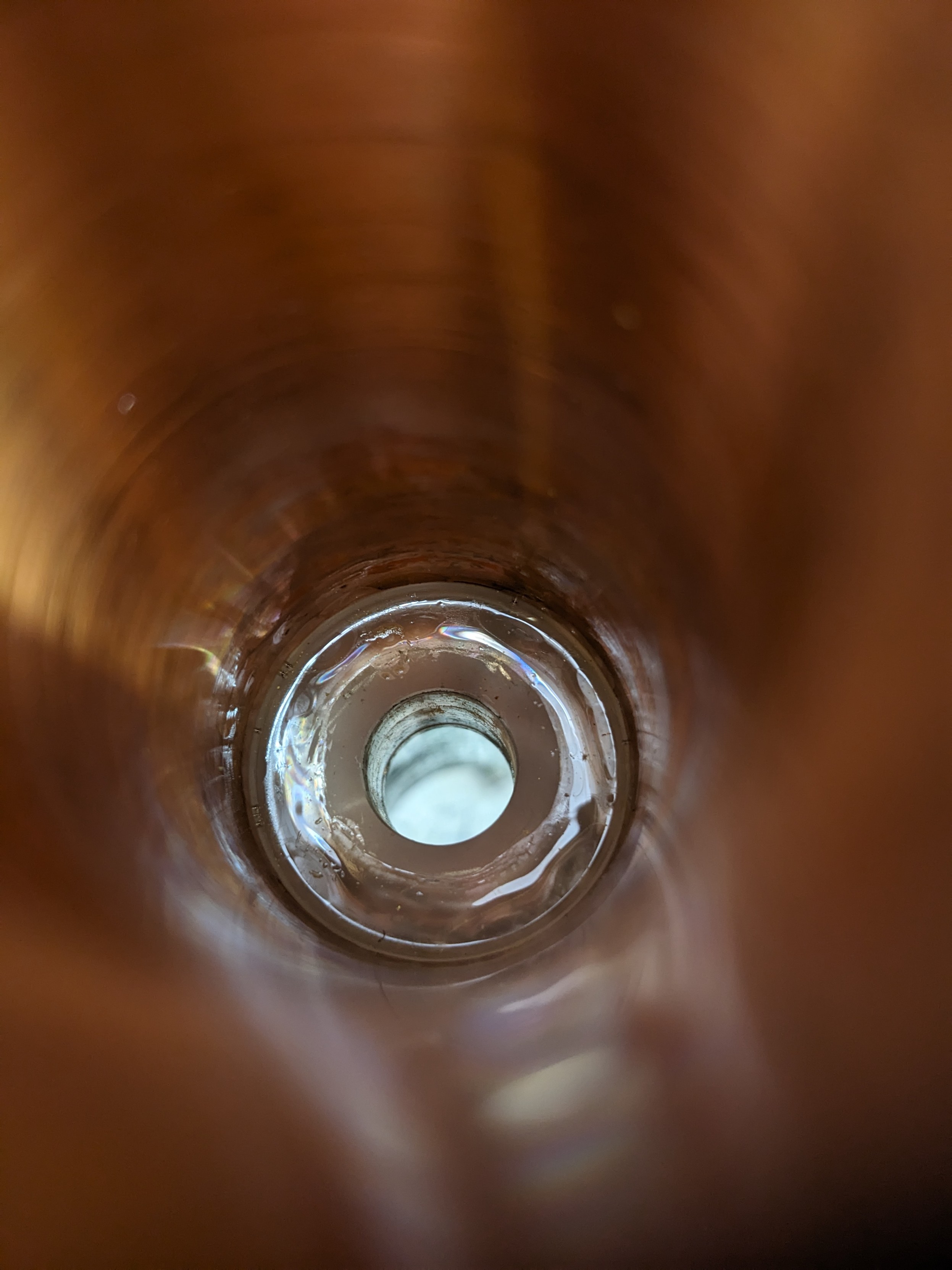
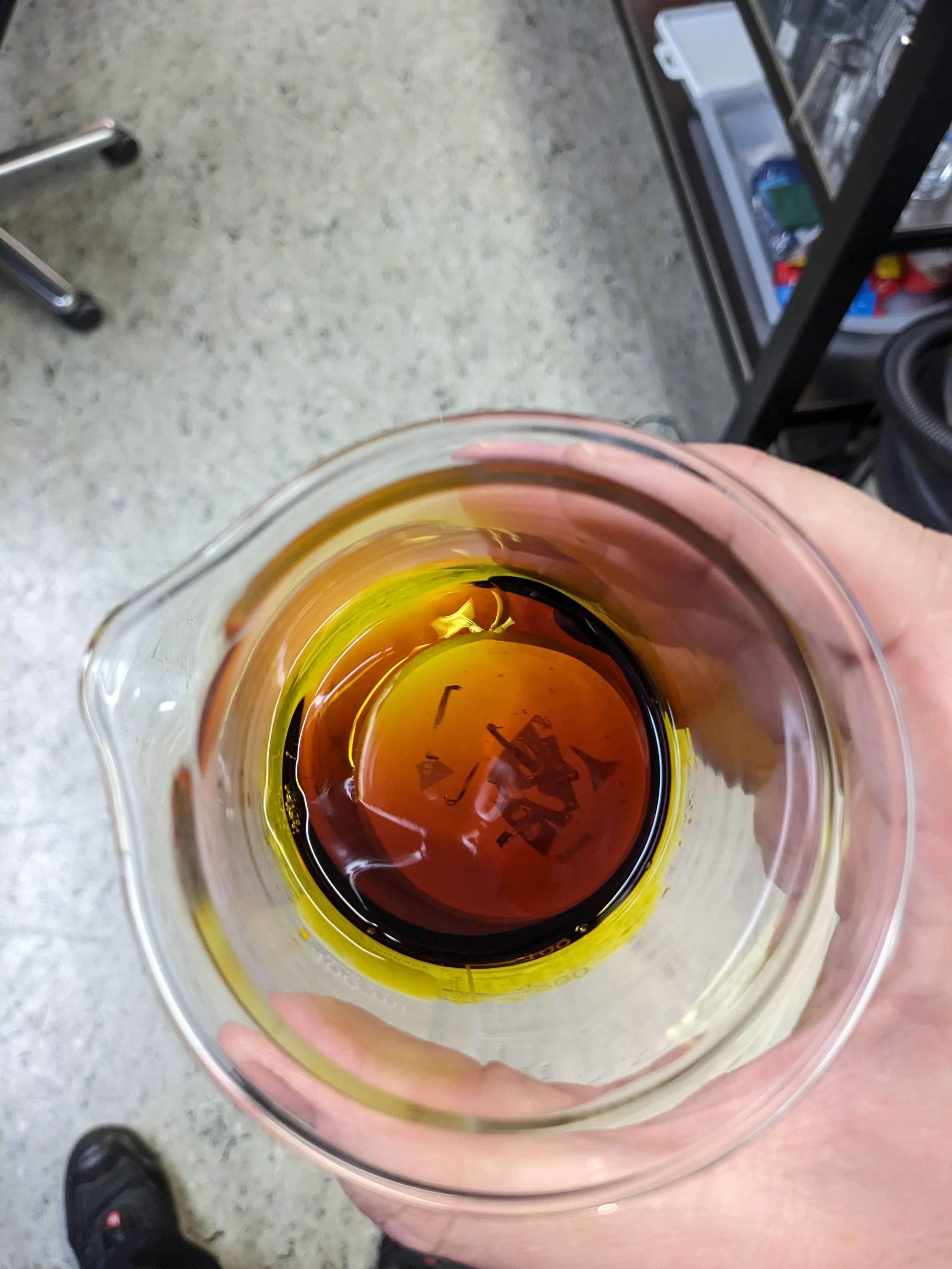
The stainless tube is the second ADR stage, consisting of ferric ammonium sulfate. This salt is slightly hygroscopic, and through years of storage it accumulated water which caused it to swell.
gigabecquerel
gigabecquerel@chaos.socialI think that's all for now, but I'm sure I forgot something. If you have any questions feel free to ask!
I'm sure there will be more images of everything, especially the magnet, as we want to take it apart to get to the NbTi wire.
Dr David Mills
Dtl@mastodon.social@gigabecquerel that's some impressive distortion of the tube due to the water absorption. How thick is the metal?
gigabecquerel
gigabecquerel@chaos.social@Dtl No clue, but I'm guessing it's pretty thin to offer good thermal conductivity.
Most stainless tubing in there was around 100 µm
penguin42
penguin42@mastodon.org.uk@gigabecquerel @stdlogicvector It's a weird collection of design isn't it - fine machine tooling, then turnbuckles and (kevlar) string, and then lots of tape.
@gigabecquerel I guess the LN2 and LHe stages work atmospheric pressure and the ADR in vacuum, right?
gigabecquerel
gigabecquerel@chaos.social@penguin42 Oh but this is pretty standard in cryo stuff!
Gotta secure the kevlar somehow, just likecall the wires
gigabecquerel
gigabecquerel@chaos.social@1183519e Yep, exactly!
The tanks just vent directly to atmosphere, or a helium recycler, ideally
gigabecquerel
gigabecquerel@chaos.socialthe magnet is doing its best not to come apart in one piece.
They used the *good* resin, as well as way too much glass fiber reinforcement.
At least too much to be any fun when taking it apart again.
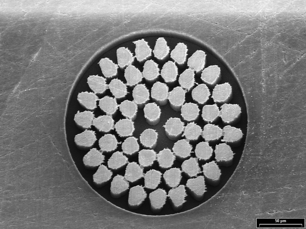
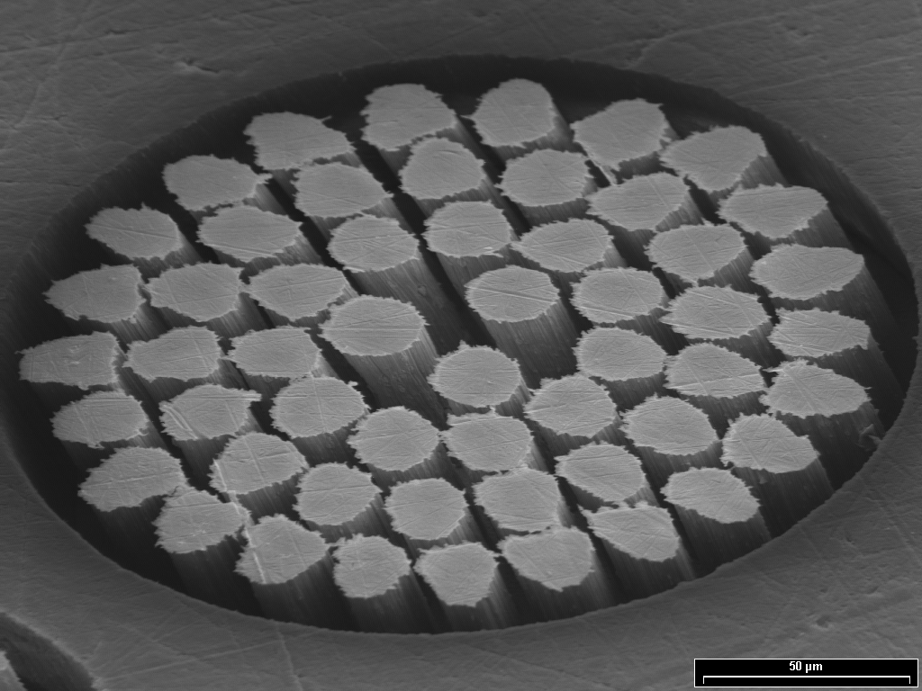
I took some SEM shots of the wire, and you can kinda see how it's NbTi embedded in a copper matrix, but to be honest, I was hoping for way more contrast with the SE detector.
BSE is broken, and EDX is in the works...
Maybe @breakingtaps has any tipps?
Breaking Taps
breakingtaps@universeodon.com@gigabecquerel Hmmm, not sure you'll see much contrast on SE. Max accelerating voltage might show some more, but I'm not able to resolve much elemental difference on mine without BSE mixed in.
Maybe some copper etching (FeCl3) to reveal the NbTi?
Really cool teardown though!
James Morris
jmorrisETA: or does it need He3 ?
gigabecquerel
gigabecquerel@chaos.social@jmorris @stdlogicvector Never seen one before, and no, it does not need ³He, just regular LHe
gigabecquerel
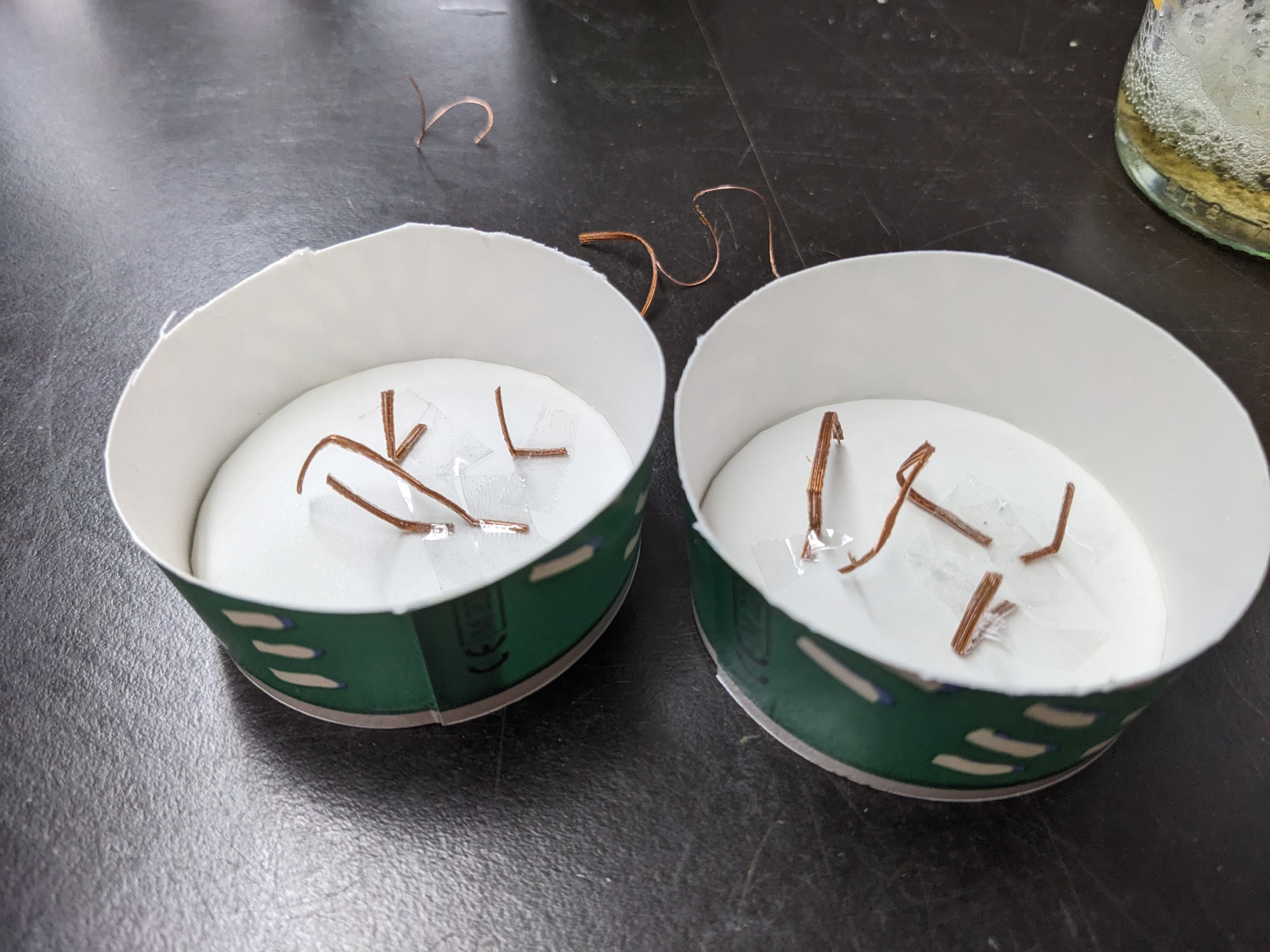
gigabecquerel@chaos.socialBetter sample preparation should do the trick.
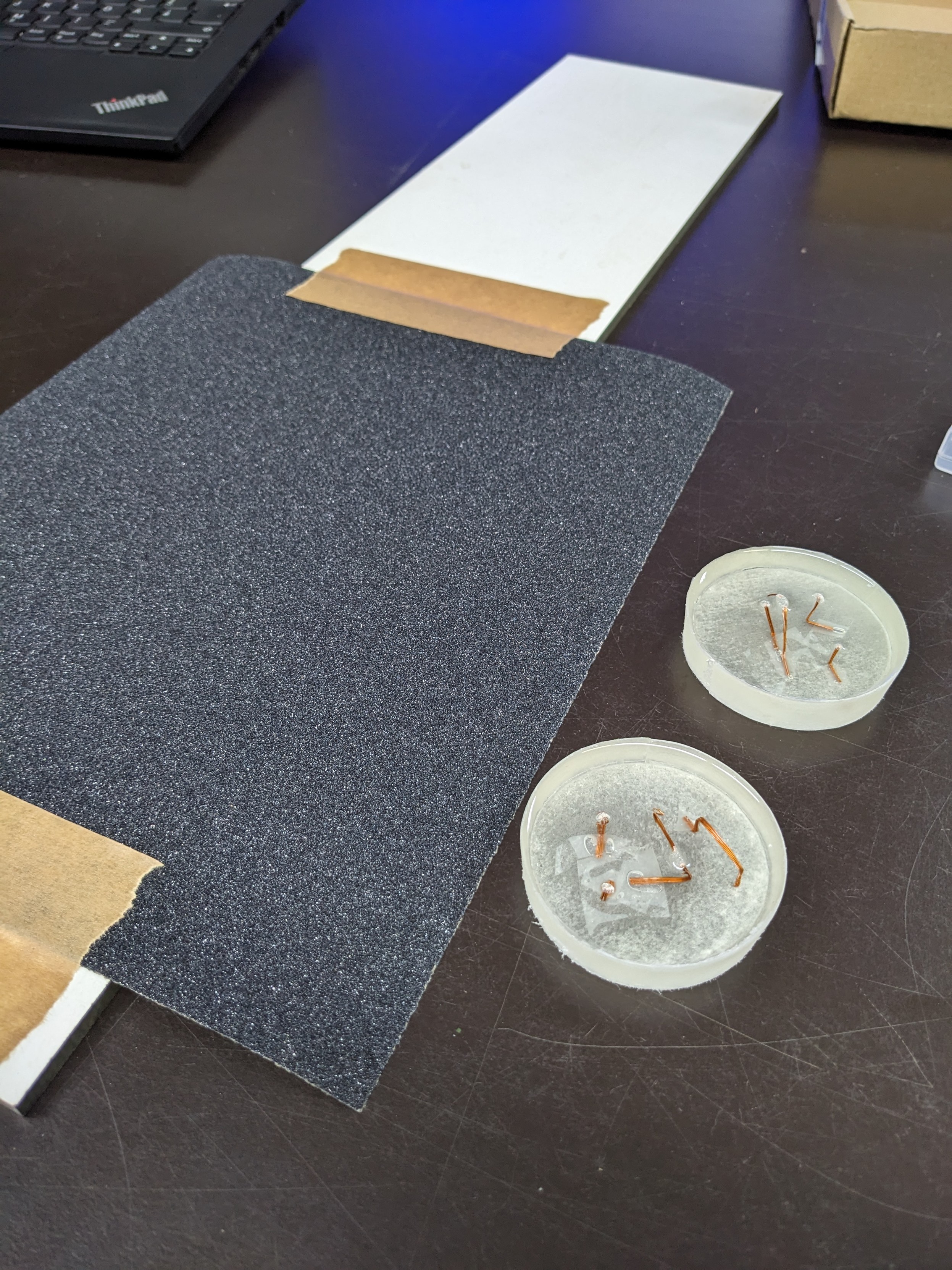
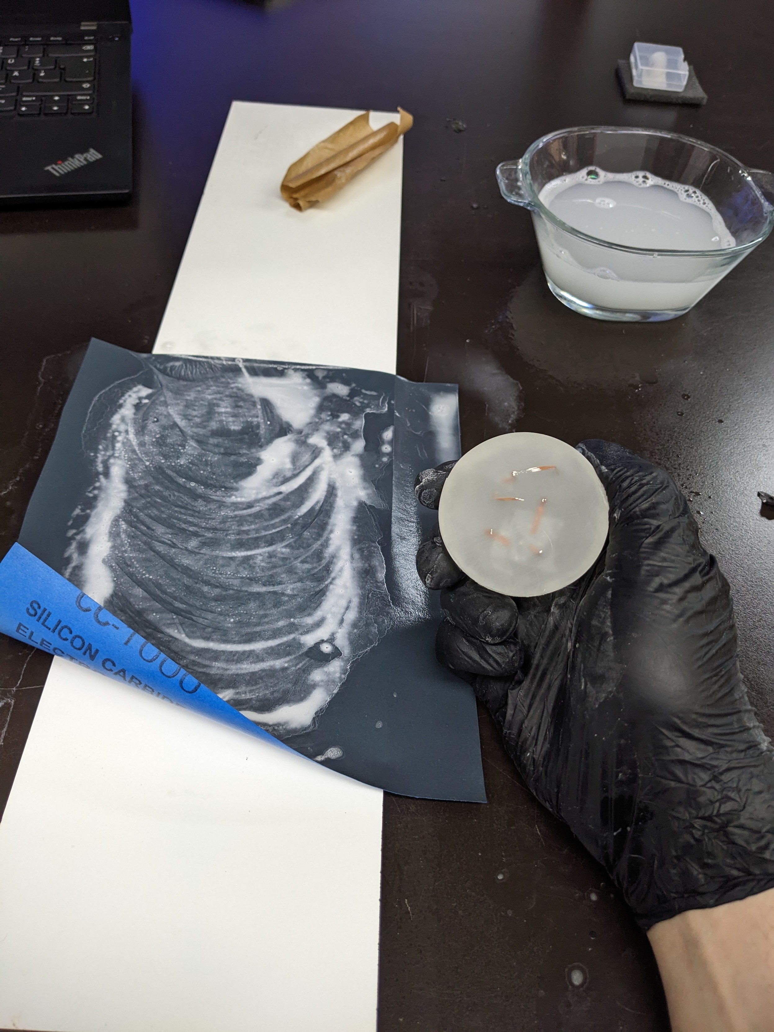
Casting two pucks of epoxy with the SC wire in all directions, one to be etched, one to be left as is after polishing.
Now comes the hardest part, waaaaaaiting
Delta Wye
DeltaWye@mstdn.social@gigabecquerel @Nixie Wooooaaah cool. I saw a datasheet on a cryostat cable assembly, I think they were talking over 2000MW in an assembly that’s under a foot (30cm) in diameter!
gigabecquerel
gigabecquerel@chaos.social@DeltaWye That sounds kinda... underwhelming?
2 GW at 110 kV (a typical voltage for such high powers ,at least here in germany) is ~18 kA, which could easily be carried by a 30 cm diameter copper wire
gigabecquerel
gigabecquerel@chaos.social@pandora Sample Preparation for the SEM
You cast something in resin, grind and polish it (and etch, optionally) to get flat and clean cross sections of stuff
https://www.ebsd.com/hints-and-tips/ebsd-sample-preparation/sample-mounting
pandora
pandora@chaos.social@gigabecquerel ah interesting… never done this kind of prep for a SEM myself
gigabecquerel
gigabecquerel@chaos.social@pandora it's my first time as well, we'll see how it turns out!
gigabecquerel
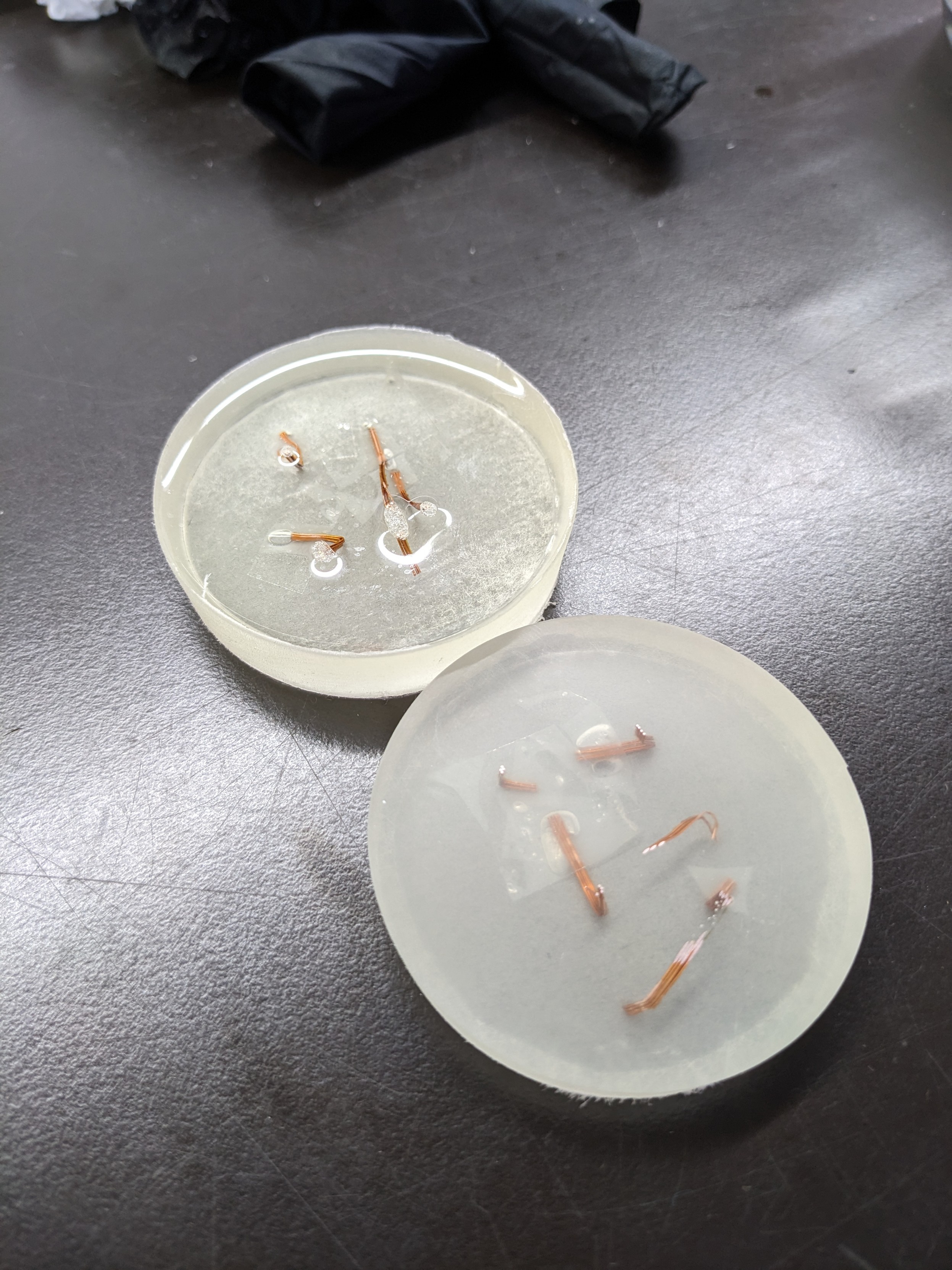
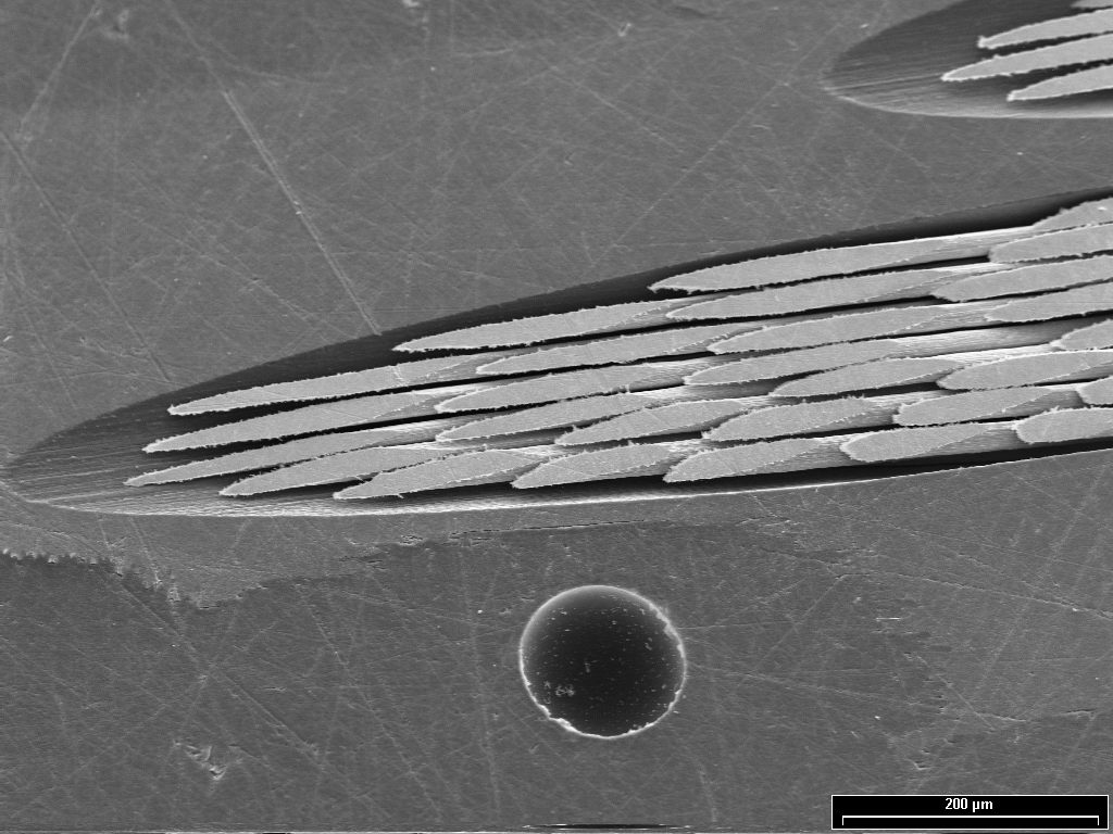
gigabecquerel@chaos.socialover night test confirmed FeCl3 etches off copper but does not attack NbTi
gigabecquerel
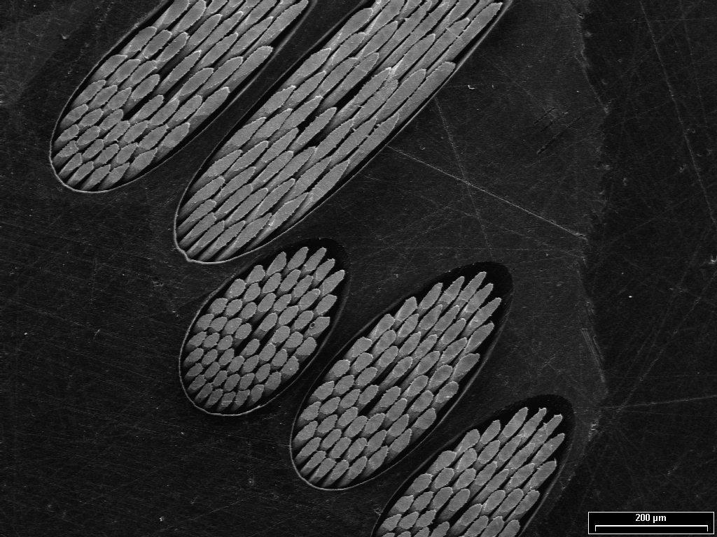
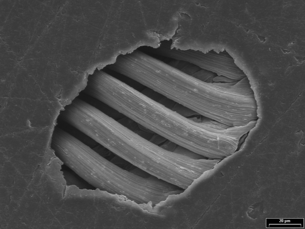
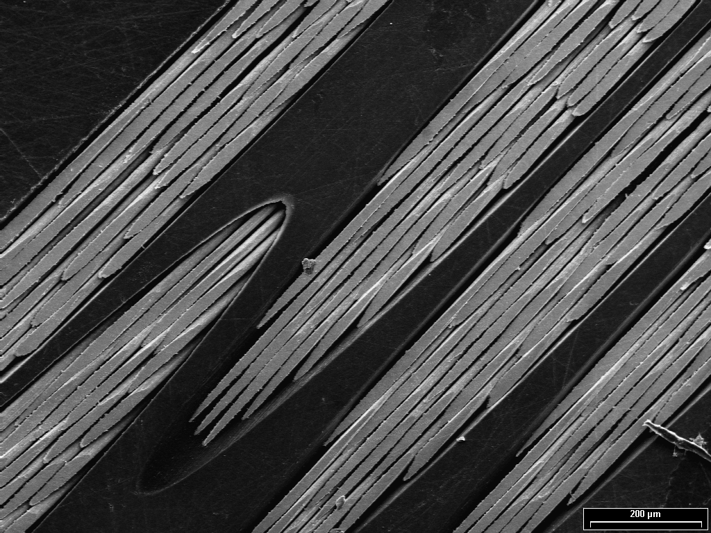
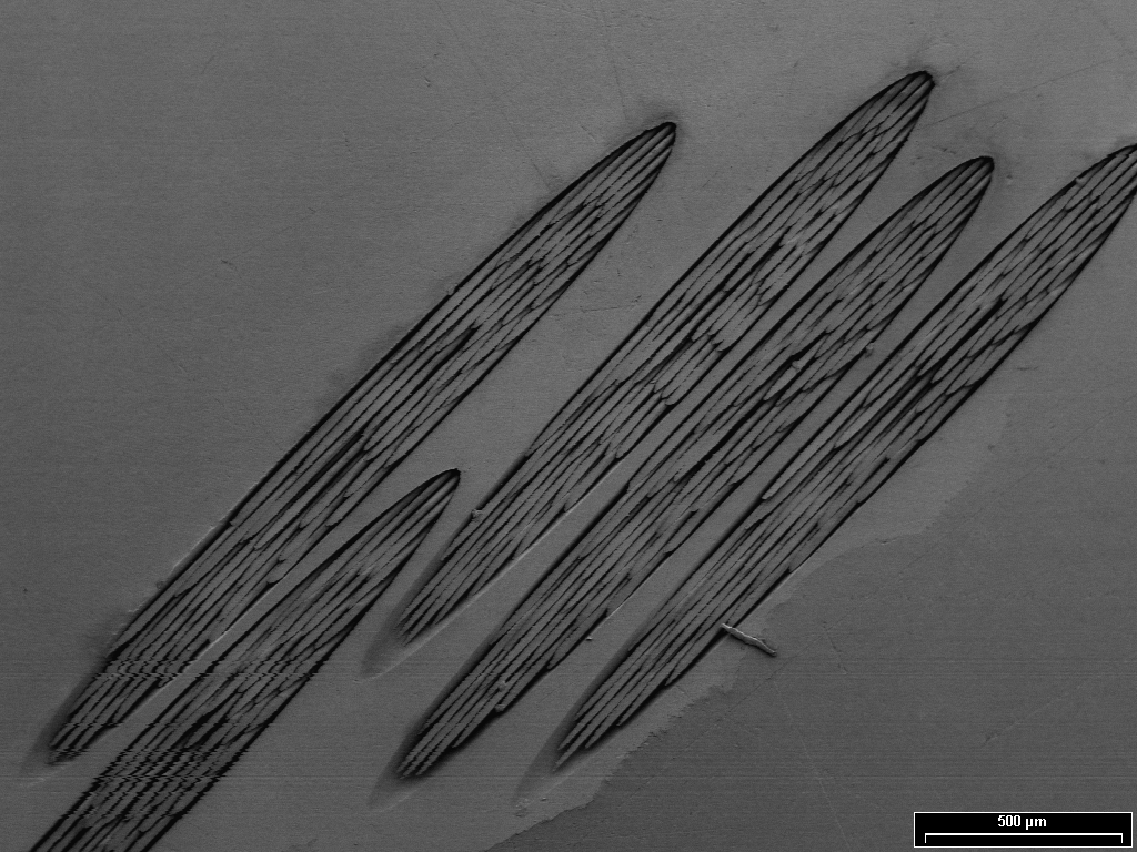
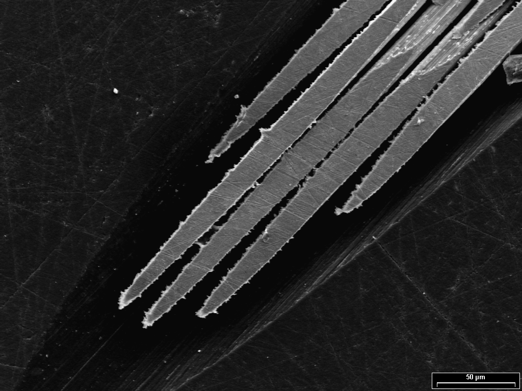
gigabecquerel@chaos.socialThese came out just so nice, I love them!
Thank you so much @breakingtaps for suggesting to etch them!
std_logic_vector
stdlogicvector@chaos.social@gigabecquerel @breakingtaps
Another image of the NbTi wires. Looks like the ribcage of a zombie horse...
@stdlogicvector @gigabecquerel @breakingtaps Look at my horse....
std_logic_vector
stdlogicvector@chaos.social@dg3hda @gigabecquerel @breakingtaps my horse is amazing!
Breaking Taps
breakingtaps@universeodon.com@gigabecquerel Oooh those etched out really nicely! Look great!
Breaking Taps
breakingtaps@universeodon.com@gigabecquerel That slanted/side etch is really hurting my brain though 😅
gigabecquerel
gigabecquerel@chaos.social@breakingtaps Right?
I don't know how to put it into words, but especially the last pic just looks *disgusting*
gigabecquerel
gigabecquerel@chaos.social@dg3hda @stdlogicvector @breakingtaps Ooo it tastes just like raisins!
std_logic_vector
stdlogicvector@chaos.social@gigabecquerel @breakingtaps Gotta view it from the right angle!


