Posts
549Following
496Followers
408📡 https://w7txt.net/
🐧 https://blog.namei.org/
☠️ https://www.facebook.com/w7txt
James Morris
jmorris
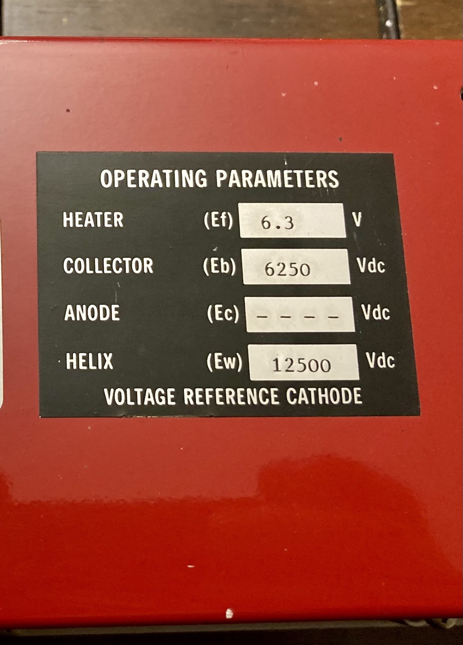
Mystery object challenge: what is this and in how many ways can it hurt you?
James Morris
jmorris
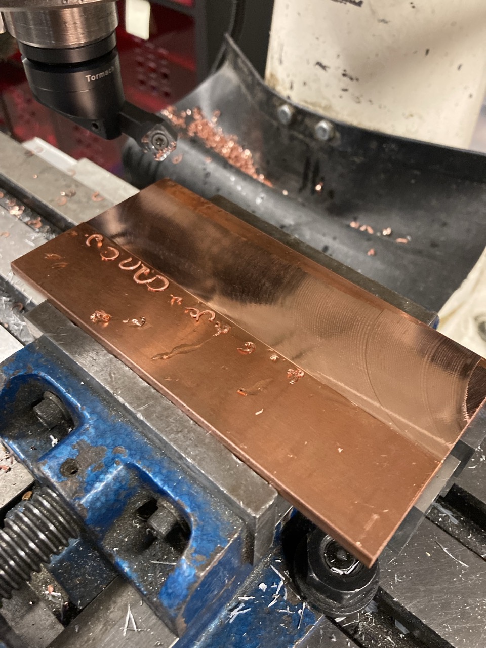
Finally learning to mill, in a work makerspace. This is a game changer for all kinds of projects. My first task is smoothing out a copper heat spreader, which was extruded and less than ideal for heat transfer.
James Morris
jmorris
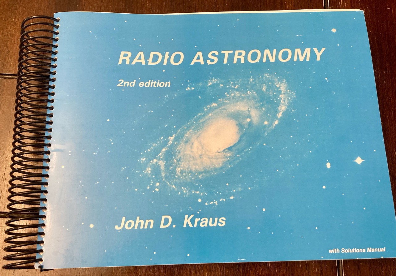
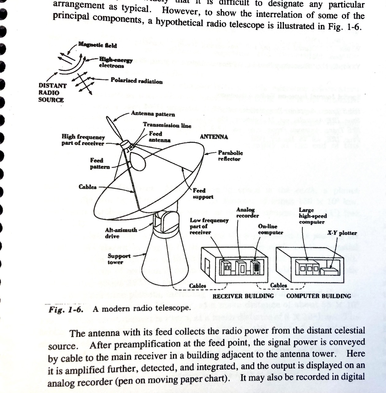
Finally bought what seems to be the bible on #radioastronomy - Kraus. I have several other books which seem to defer to Kraus on some of the “basics”. Good to have all of the essential information in one place. Seems this book is only currently available as ring bound or a cheap paperback. One specific goal I have here for 2024 is to properly understand wave polarisation & Stokes parameters.
James Morris
jmorris
Edited 1 year ago
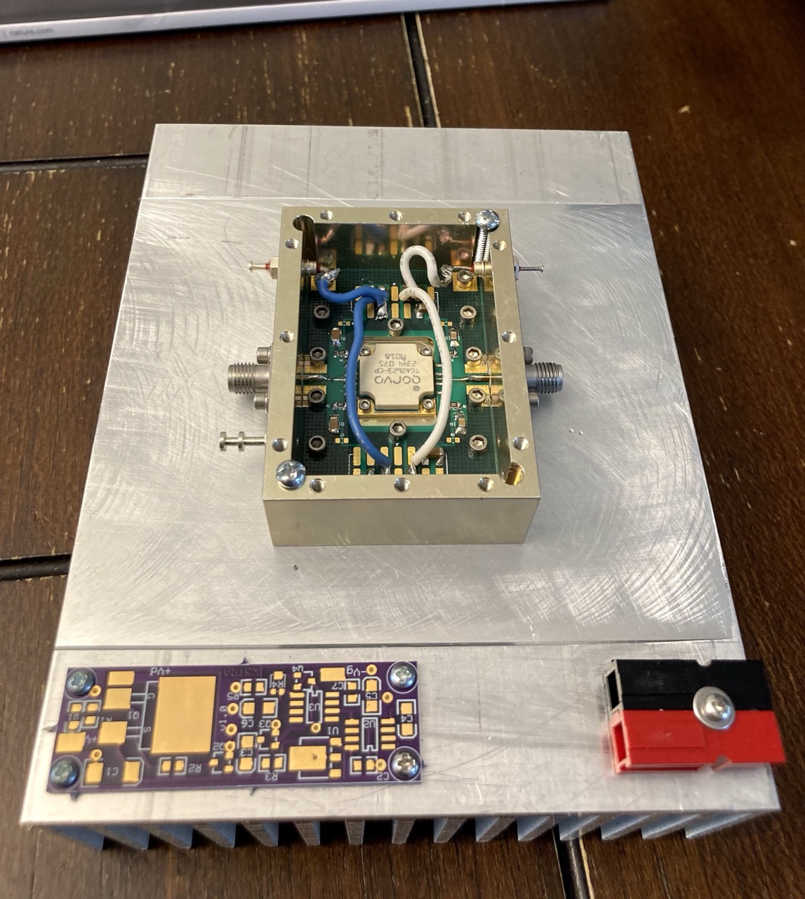
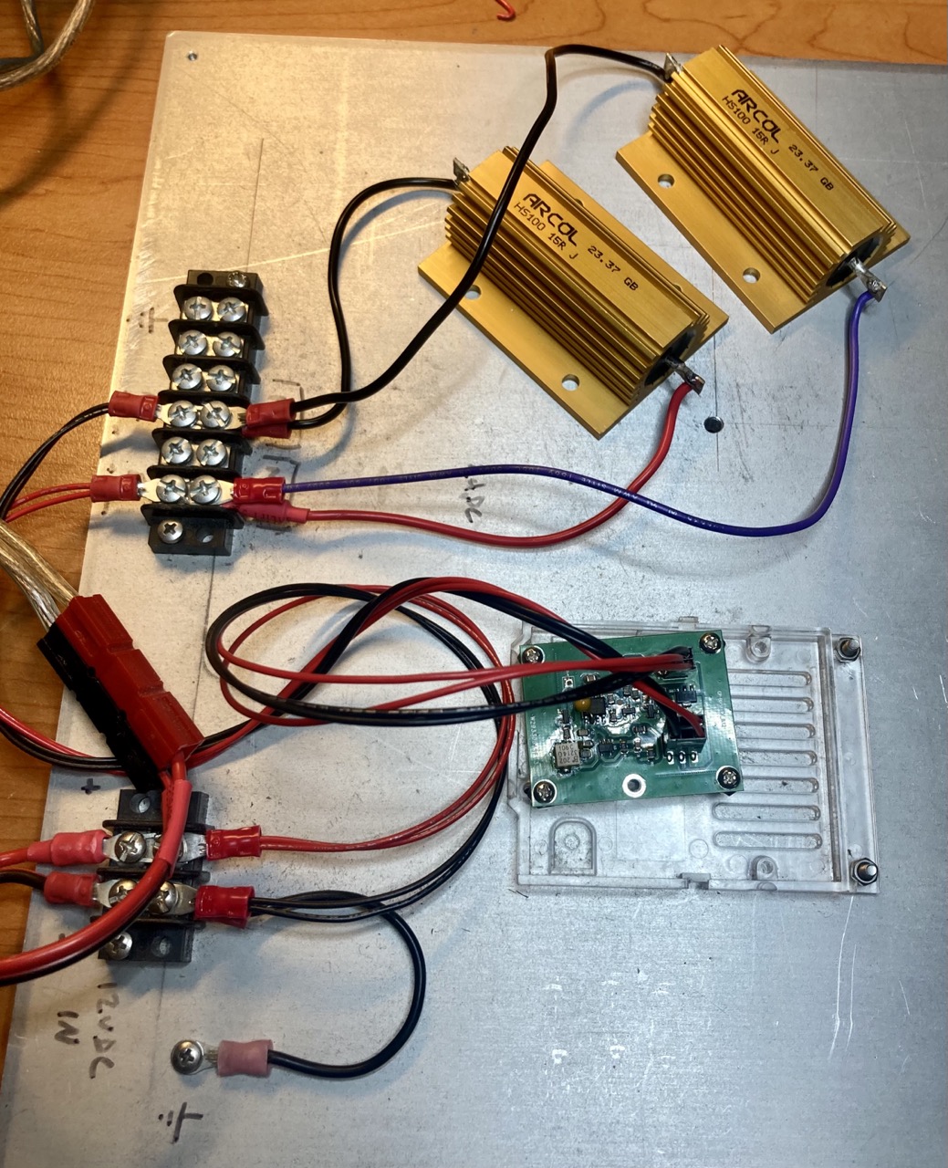
Finished making a thing. This is a power supply for the 30W 10 GHz amplifier I’m working on. It should also be able to power the transverter, IF radio, & relays. I’m resisting the temptation to add an MCU and display. For now.
(Note: the 50 Hz label should say 60 Hz)
#hamradio #electronics #amateurradio #microwave #qro #sspa
(Note: the 50 Hz label should say 60 Hz)
#hamradio #electronics #amateurradio #microwave #qro #sspa
James Morris
jmorris
Close up of the thermistor, which is a tiny bead in the middle of the photo.
James Morris
jmorris
Ok, I think I understand this a little more now. The horizontal bar in the waveguide is a thermal mass, which heats up in the presence of RF. The detector thermistor is attached to it (too small to see here), and it will closely follow the temperature of the bar. A bias current runs through the thermistor, and also the isolated compensation thermistor. The comp thermistor has its own thermal mass, which is the gold plated square, and a couple of rectangular blocks, which I assume were selected and pasted in by hand during construction, and this can be finely adjusted via the screw. Not sure exactly where the compensation thermistor is yet, and the circuit diagram shows a capacitor here somewhere. Could be both are in the white block, which looks like a modern SMD cap.
James Morris
jmorris
Edited 1 year ago
Not sure if this microwave power sensor is repairable. It’s an HP P486A waveguide thermistor mount for 12.4 to 18 GHz. It was bugging out, and I’ve rejuvenated one of these before (using the guidelines in the manual) but it didn’t work this time. I’m puzzled by the mechanics of this, what the adjustment screw actually does, and why is it attached to a small metal block which is maybe held with conductive paste? It’s supposed to finely match the inner and outer thermistors: one is in the waveguide and the other is inside the housing as a reference. The waveguide thermistor is heated by the RF signal, and the power meter detects this, via a bridge circuit which tries to balance the current in each thermistor.
The wonders of 1960s microwave tech. We explored space with this stuff.
#hamradio #amateurradio #microwave #electronics
The wonders of 1960s microwave tech. We explored space with this stuff.
#hamradio #amateurradio #microwave #electronics
James Morris
jmorris
Edited 1 year ago
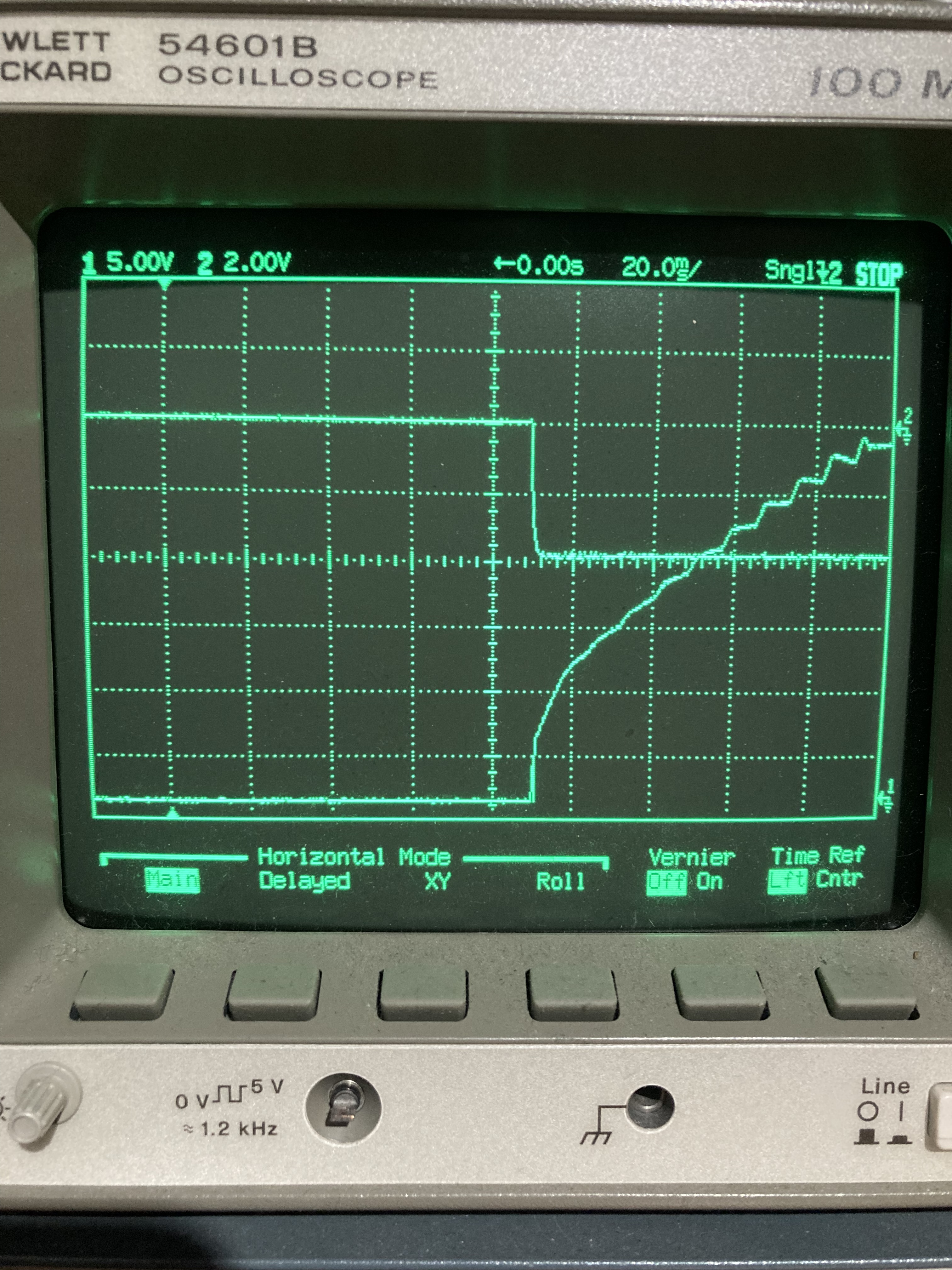
Here's a trace of the power up sequence, with the gate voltage at the top, and drain at the bottom. I'm not sure if the CRO is fast enough to catch the sequence correctly, because I can't tell if there's a gap between gate & drain. IIUC, the negative regulator chip provides a 'voltage ok' signal that is used to switch the gate, so it should be ok. But, I'll keep investigating until I'm sure.
This is the kind of thing that leads to long development times for amateur microwave radio projects, so many (fascinating) rabbit holes and a lot of learning as you go. I wonder if more people knew about this aspect of the hobby, whether we'd see more and younger people joining.
This is the kind of thing that leads to long development times for amateur microwave radio projects, so many (fascinating) rabbit holes and a lot of learning as you go. I wonder if more people knew about this aspect of the hobby, whether we'd see more and younger people joining.
James Morris
jmorris
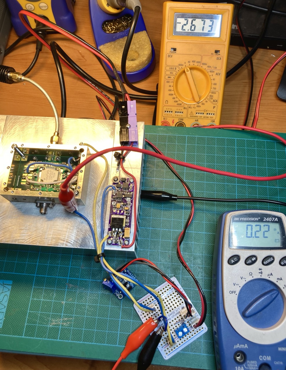
Load testing the bias power supply. The amp uses an expensive ($650) GaN transistor which must have bias applied before main power, or it will be destroyed - it’s ‘on’ by default and needs bias to switch ‘off’. I’m being extra careful with this, will also verify the power up sequence on a scope, response to short circuit etc.
James Morris
jmorris
Edited 2 years ago
Just a warning for people thinking about getting into #microwave #amateurradio -- it's an infinite labyrinth of hobbies, knowledge, and equipment. Precision machining, stripline circuits, strange semiconductors (IMPATT diode amplifier, anyone?), exotic electron tubes (which will try and kill you via xrays, lethal voltages, and beryllium oxide), metrology, physics, DIY, vintage equipment resurrection, morse code (modulation? sheer luxury!), scouring ebay, haunting electronics stores, poring over poorly scanned service manuals from defunct companies, and too many hex keys.
Oh, and it's a gateway drug to #radioastronomy.
#hamradio
Oh, and it's a gateway drug to #radioastronomy.
#hamradio
James Morris
jmorris
Now using aluminum extrusions to adjust the position of the sensor & also hold it tight. Any further improvement will require a dial indicator to ensure it’s centered. And maybe some shims. Learning a lot about precision metalwork with this.
James Morris
jmorris
Making some hopefully final mods to the azimuth sensor for this az/el drive. Spent ages trying to find screws to match the Hammond enclosure. Turns out to be M3.5, which I have never seen used before. #hamradio #amateurradio #microwave #radioastrnomy
